Product News
February 25, 2019
eHS: The Nanosecond Power Electronics Solver Whose Time has Come

What is eHS: The Nanosecond Power Solver?
“The OPAL-RT electric Hardware Solver (eHS) is a powerful floating-point solver… that enables users to simulate an electric circuit on an FPGA automatically, without having to write the mathematical equations.”
“It combines the simplicity of building electric circuit models using the new OPAL-RT Schematic Editor, SimPowerSystems Toolbox, PSIM, the PLECS Blockset, or NI Multisim software with the strength of OPAL-RT FPGA-based simulators to solve the currents and voltages within the circuit in real-time, with a sample time below 1 µs.”
“The eHS solver uses modified nodal analysis. It solves a conductance matrix to find the voltage at each node of the circuit, and the current in each branch. The conductance matrix of the circuit is made independent of the switch control signals through the implementation of the Pejovic method representing the switch impedance. With this method, a conducting switch is represented as
–eHS User Guide
Commentary: Luc-André Grégoire, one of eHS’ Developers
“eHS—our electrical/electronic Hardware Solver—is like all simulation tools, but uses a smaller time-step, and so an FPGA is required. An FPGA may not be intrinsically any faster than a CPU, but since it’s dedicated to a sole task and closer to the hardware layer, it is able to act a great deal faster than a CPU can. We also use FPGAs to acquire I/O closer to where the computation is required, and this reduces electrical latency. eHS is like an impartial third party—it’s an electronics solver, but it can be run on various kinds of hardware: on RT-LAB, HYPERSIM, or on a National Instruments (NI) platform.”
“Having said all that, yes: it takes an FPGA because of the much-reduced time-step. When we talk about eHS x128, that signifies sub-microsecond simulation up to about 125 states in 1 microsecond. That’s equivalent to 20 three-phase two-level inverters on a single FPGA with no delays (since it’s all within a single solver core)—and the ‘no delays’ part is obviously crucial when you’re working with extremely short timesteps.”
“In general, the more operators in the solver, the bigger and faster the circuit that can be solved. Additionally, the more operators in the solver, the more resources and hardware that are then required—and thus the footprint required by the resources for the solver is also larger. We’ve looked at clustering these FPGAs: for a Québec client, they were considering three FPGAs, with each of these having two times x128s. This is significant computing availability.”
“What we used to do about a decade ago on
“As we started to work more on FPGA, we first thought, ‘this is a much smaller time-step; we no longer need to interpolate’. However, when we went to a smaller time step, customers told us they wanted to go with a much faster switching frequency. A higher switching frequency meant that we needed to be much more accurate on the pulse. So we re-introduced the interpolation, but now on FPGA.”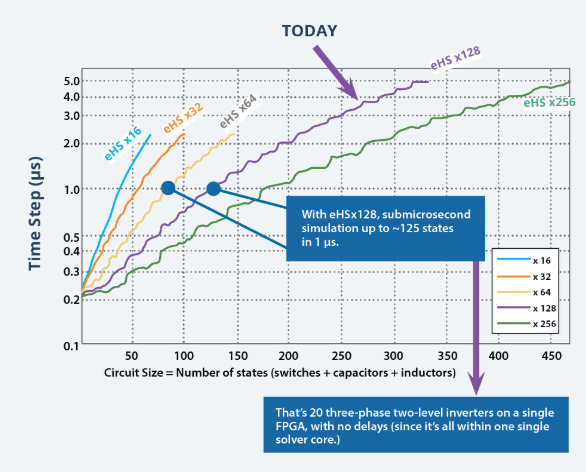 “The interpolation tool was applied to CPU, and now we use the same kind of ‘trick’ on FPGA—but we’ve modified it to reach a higher performance than it used to achieve, and to support more things. This ‘trick’ is similar to what our RT-EVENTS block set does, which, in turn, is part of the CPU-Based Electrical Toolbox in RT-LAB (and soon in HYPERSIM, as well). The intended use for this is converters switching at faster than 20 kHz, so resonant converters–or enhanced accuracy on the switching events.”
“So if you have some cascaded H-bridges that are supposed to be phase–shifted, and although they’re switching at low frequency, you still need to be very accurate on the switching events: this could be an application. You could also talk about ultra-high frequency DC-DC converters using GaN (gallium nitride) devices, with maybe 100 kHz switching frequency—this eHS implementation is a solution to some of these problems.”
“You mentioned MMC in HVDC to me earlier, with mixed converters. Ultimately, eHS is for high-switching converters, and eHS is very good because it’s a fixed matrix solver—but there are some drawbacks with that topology. Converters that use multiple switches in series may not be the best candidates for eHS, but with the technology we’re proposing, we use a number of switches, and manage to get around that as well.”
“What is genuinely new about this is that OPAL-RT was the first company to introduce a time-stamped bridge around 20 years ago. This method allowed sampling of a PWM signal at a much higher rate than the simulated model. This new technology is now available in our latest eHS solver, where a PWM signal can now be sampled at a rate of 200 MHz, or every 5
“Sampling of the PWM going up to 1 MHz, while maintaining 99.5% accuracy, can be achieved. (For comparison, in earlier versions of our software, PWM frequency was limited to 20 kHz to obtain similar fidelity.) Additionally, using our patent–pending modelling approach, any 2-level or 3-level converter topology (full–bridge, NPC, T-Type, Pack-U cell, flying capacitors) can be represented, even during blocked or discontinued operations.”
OPAL-RT Award for eHS: Prix Innovation PME 2018 @ ADRIQ-RCTi Gala
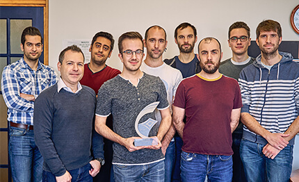 We are very pleased to announce that OPAL-RT TECHNOLOGIES has received the prestigious Prix Innovation PME 2018 yesterday evening at the ADRIQ-RCTi Gala, Montreal, for its innovative product eHS–used by our most innovative clients all around the globe.
OPAL-RT TECHNOLOGIES would like to give a big thanks to all of our developers and researchers, and to all of those who worked actively on the product. Special kudos to Sébastien Cense, Tarek Ould Bachir, Luc-Andre Gregoire and Christian Dufour who have worked on eHS since its creation.


